| J. Jowett | Daresbury Annual Meeting | Nuclear Beams at HL-LHC pdf pptx |
| M. Schaumann, J. Jowett | ColUSM#21 | Ion impact distributions on DS collimators in IP2 pdf pptx |
| J. Jowett | ColUSM#5 | IR2 collimator positions to intercept BFPP and EM dissociation products pdf |
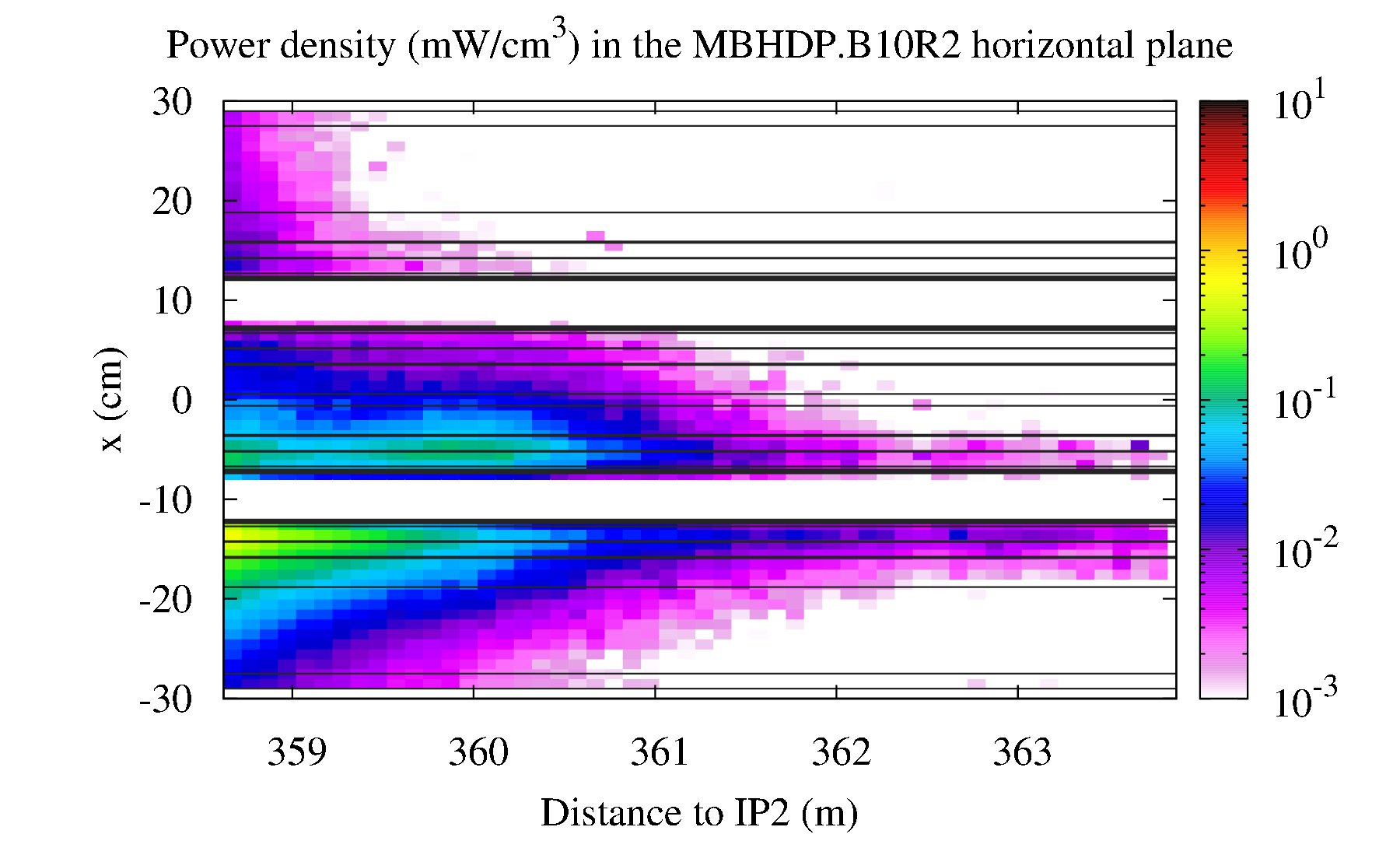
In IR2, during Pb-Pb collisions, different Ultraperipheral processes produce varous debris. The processes considered here are Bound-Free Pair Production (BFPP) and Electro-Magnetic Dissociation (EMD). The debris created are Pb ions with different masses and charges, hence different magnetic rigidity than the main ion beam. They behave as separated secondary beams. These secondary beams will be lost as soon as the dispersion is large enough, in the Dispersion Suppressor, as shown in the following figure.
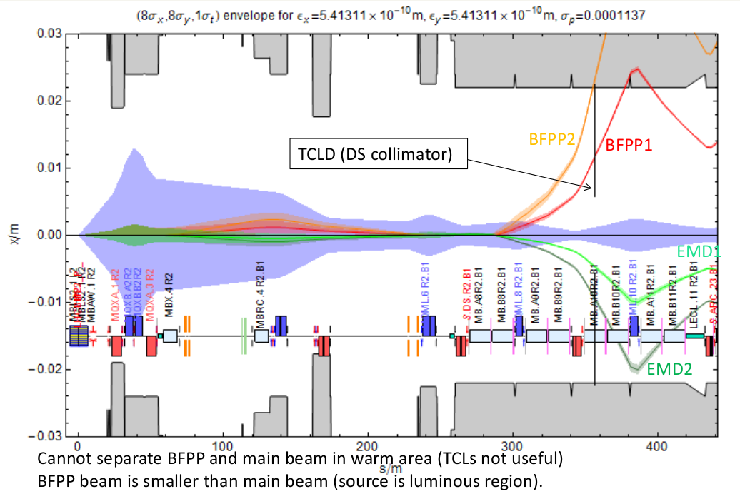
Beam envelopes on the right side of IP2. Main beam is in blue, secondary beams are labeled with the corresponding process name. Aperture is in grey, with the same vertical scale as the beams.
The most sensitive secondary beams, in matter of energy deposition, are BFPP1 and EMD1. The installation of one DS collimator in cell 10 would allow to intercept them before they hit the aperture, while keeping a big enough retraction with respect to the primary beam. The installation would be similar to the DS collimator in IR7: the 8.3T dipole MB.A10R2.B1 would be replaced by two shorter 11T dipoles, creating extra space for a collimator.
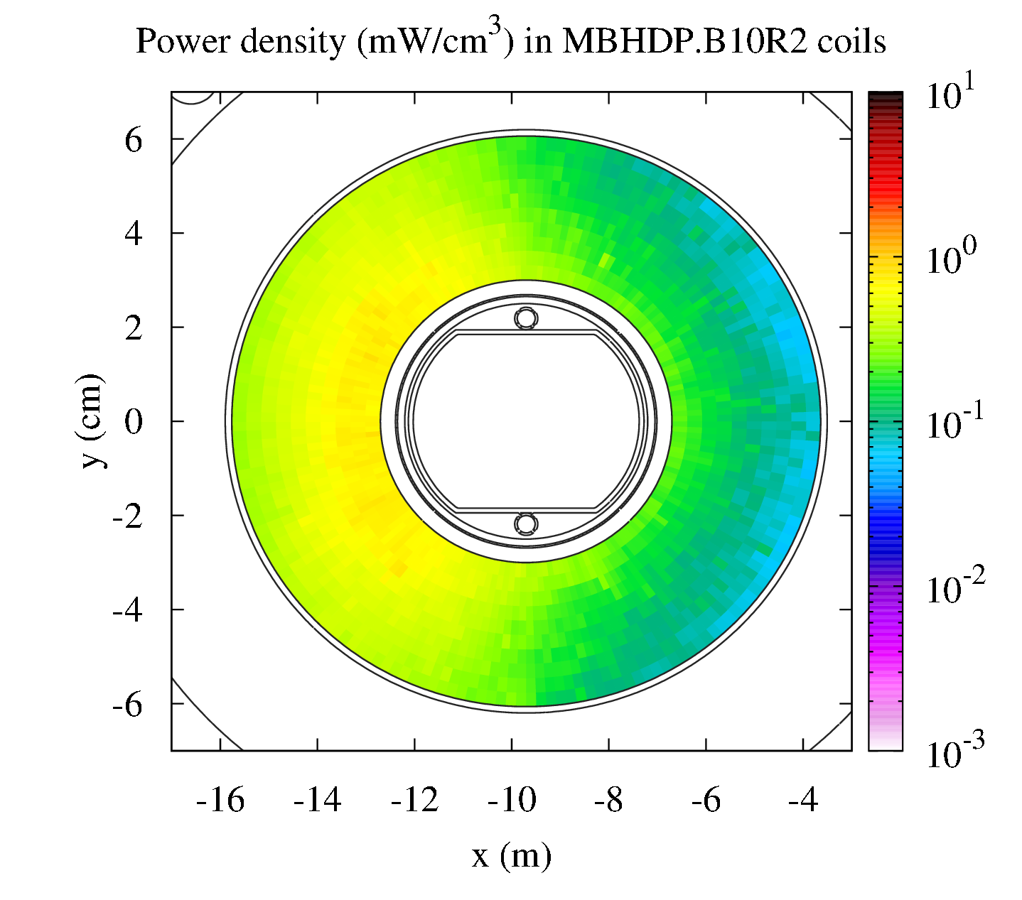
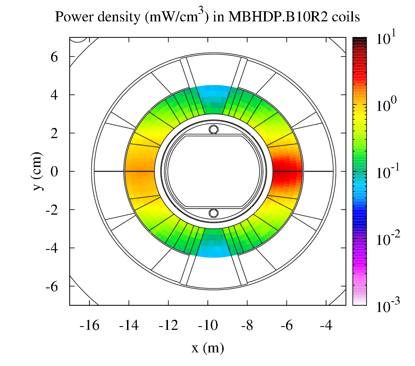
The maximum power density for upgrade luminosity is expected to be around 93 mW/cm3. More details on energy deposition have been presented by A. Lechner (pdf).
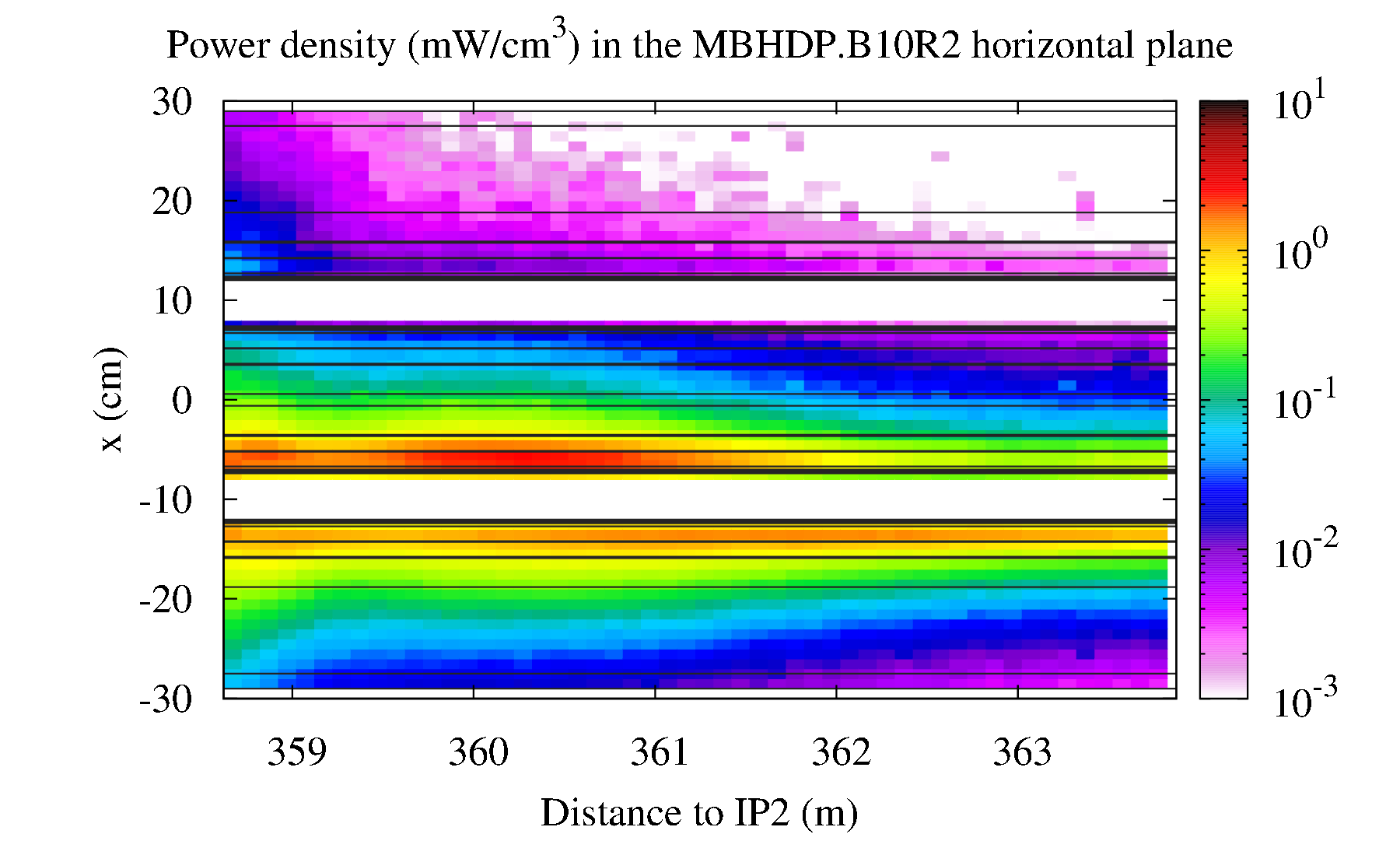
The measured losses in the LHC around IR2 during the Pb-Pb runs of 2011 show that the highest BLM signal is indeed in the BLM associated to the quadrupole 10R2, a few meters behind the dipole A10R2, as hown in the following figure.
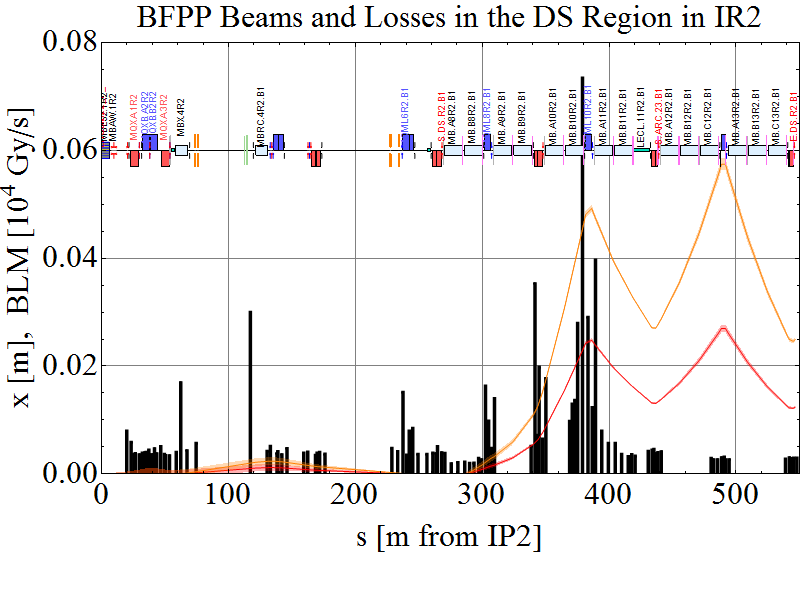
Beam losses, integrated over 83s, for the right side of IP2 (black histogram), and secondary beams associated with process BFPP1 (red) and BFPP2 (orange). The losses are the highest around quadrupole 10R2.
Installation of collimators in the Dispersion Suppressor (DS) to both sides of ALICE (IP2),
to intercept secondary beams from bound-free pair production (BFPP) and electromagnetic dissociation (EMD).
This was presented and discussed during ColUSM #21
| M. Schaumann | Ion impact distributions on DS collimators in IP2 pdf pptx |
TWISS files for B1 and B2 calculated for the circulating 208Pb82+ beam with the new layout
| Twiss B1 | Twiss B2 |
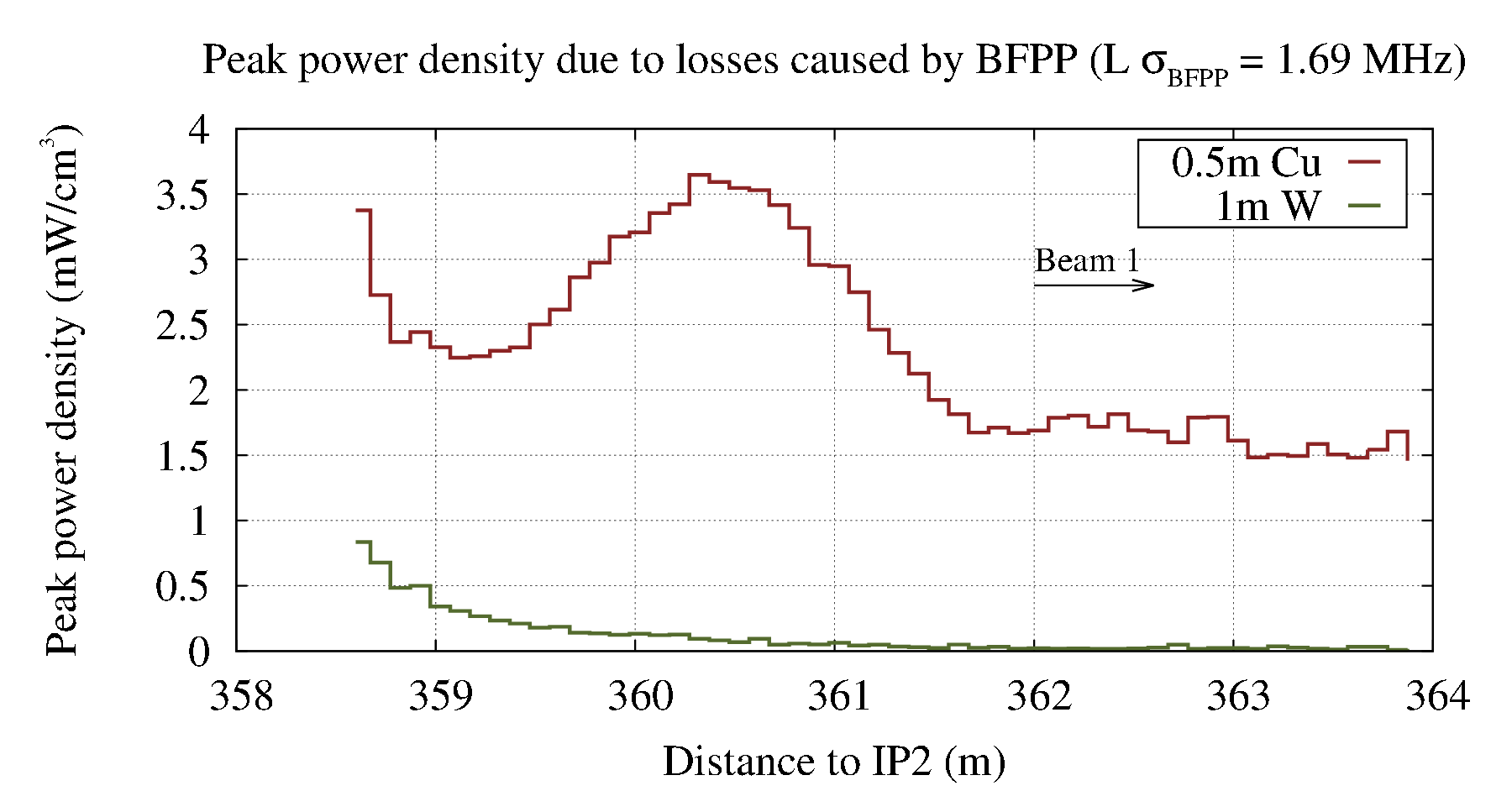
Simulations of energy deposition in the 11T dipoles for different Dispersion Suppressor Collimator models (courtesy of G. Steele). Two "extreme" cases were simulated: a 50 cm copper jaw, and a 1m Tungsten jaw. Full presentation:
| G. Steele et al. | DS Heat Load Scenarios in Collision Points and Cleaning Insertions pdf pptx |
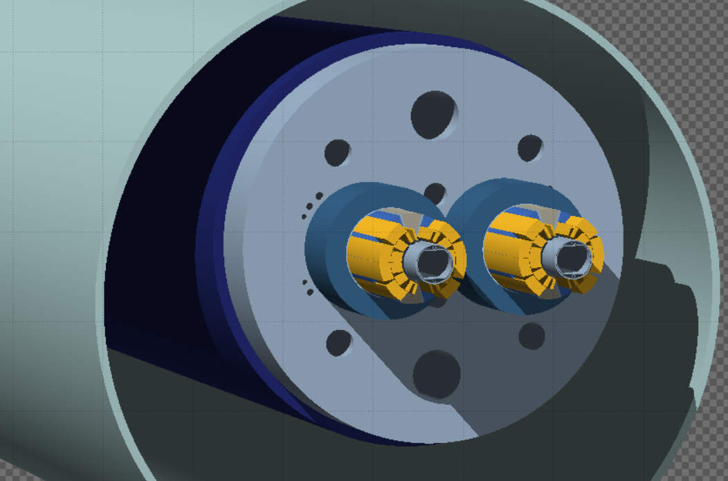
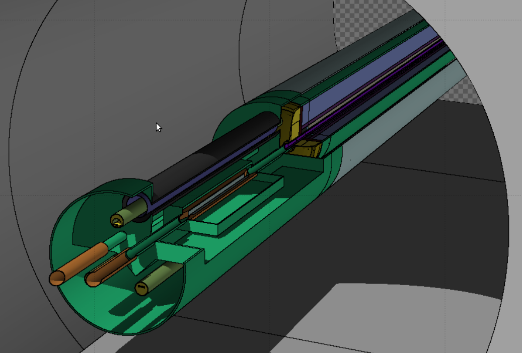
FLUKA models of the 11T two-in-one dipole and the TCLD collimator assembly.
| Peak power density (mW.cm-3) | Reduction Factor | Peak Dose (MGy) for 10 nb-1 | Total power on magnet (W) | Total power on jaw 1 (W) | Total power on jaw 2 (W) | |
| MB - No collimator | 95 | 1 | 20 | 105 | N/A | N/A |
| 1m Tungsten | 0.8 | 114 | 0.2 | 8.4 | 77 | 13 |
| 0.5m Copper | 3.7 | 2.6 | 0.8 | 46 | 42 | 6.5 |
| 1m Tungsten, 2mm half gap | <0.1 | >900 | <0.1 | 3.0 | 96 | 6.5 |